Category: Converter Manual Article
-

Supercycle simulation
Why simulate a supercycle See FGC yellow pages: https://accwww.cern.ch/proj-fgc/gendoc/def/PropertyFGC.htm#FGC.CYC.SIM Use this functionality if you wish to test a converter with your own cycles (equivalent to using "local timing" in the old electronics): Be aware of the dangers Simulating a supercycle should never be made when there is beam in the machine because it bypasses the
-
No-PPM, PPM and Multi-PPM
These behaviours are set by the properties DEVICE.PPM and DEVICE.MULTI_PPM in the FGC3 configuration This behaviour is requested by the CCC, it is also set in the CCDB and does not normally change during the lifetime of a converter. Background The CCC controls when a power converter starts playing a user function by means of
-
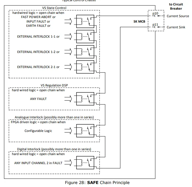
Converter “safe” protection chain principle
Each RegFGC3 card can act on the protection chain of the converter. The protection chain acts on SKMCB pins 10,11 which controls the undervoltage coil of the MCB and interrupts the circuit immediately. The state machine for example has several inputs that act on this chain;
-
REF.ECONOMY.DEST.MODE
1) Put converter in OFF or BK state: S PC BK 2) Disable this property to disable the destination-based economy mode: S REF.ECONOMY.DEST.MODE DISABLED In the SPS there exists another economy mode that can be disabled in this way: S REF.ECONOMY.MODE DISABLED 3) Put converter in CYCLING S PC CY Yellow pages link to property:
-
LOAD.I_SAT_GAIN
Read also the yellow pages reference and the FGC block diagram This needs to be set to 1 if we want the saturation model to be taken into account.
-
unblock synchronisation
In case of "bad state" response when typing S CONFIG.MODE SYNC_DB you can type the following command to reset the synchronisation state: S CONFIG.STATE RESET Then try again S CONFIG.MODE SYNC_DB
-
DSP HEX switches
The HEX1 and HEX2 switches are decided based on the following rule that combines the converter information and switching frequency information into one Hex code: 2^(TypeNum) x (Fsw,H-bridge + Fsw,boost) For example for SIRIUS S with type number=10: 2^(10) x (6500+13000)=2.00E+7 (rounded up) Hex 2 is defined by the decade (=7), Hex 1 by the
-
LIMITS.I.EARTH
This FGC property has no effect as a trip level (which is fixed inside the state machine card). You set this to be the voltage level that trips the converter. The trip level is 0.6V (=0.006A) for SIRIUS and is defined by the rail of the comparator in the state machine card. When you set
-
Highly saturating magnets and pre-functions
The duration of a pre-function is "predicted" by the FGC doing a basic calculation dt= (L*di)/(V+RI) and hence the FGC knows when to start the pre-function in order to arrive on-time for the beam extraction. However, in case when a heavy magnet saturation takes place (typically at high current only), the calculation is not correct
-
Create TABLE function
# Produce a unipolar square waveform # using a table function #first disable the user looking to modify !S REF.FUNC.PLAY(2) DISABLED ! S REF.FUNC.TYPE(2) NONE #Define a trapezoidal table for User 02 ! S REF.TABLE.FUNC.VALUE(02) 0|0,0.40|0,0.5|100,0.6|100,0.7|0,1.2|0 # set the user 02 function to be TABLE ! S REF.FUNC.TYPE(02) TABLE ! S REF.FUNC.PLAY(02) ENABLED # Make