When the circuit inductance is very low (1.4mH in this example). If identification was made with PowerSpy to calculate the differential inductance Ld = (Vmag- rmag x Imag)/(di_dt), with a very low inductance the accuracy of the calculation for Ld is a function of how accurate the measurement of rmag was made in DC (at current higher than 10-50A) and the di/dt used during your ramp: di/dt shall be high in order to have a significant inductive voltage drop across the magnet. Please recheck both points.
- There’s a coupling which is significant between the load and the output filter: SIRIUS_S is [600uH + 2x70uF + 2x80mOhm] in // with [0.3125 Ohm – 1.4mH]
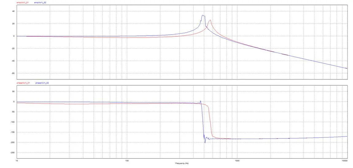
In blue, the bode plot of the filter with a circuit composed of 0.3125 Ohm and 10mH: decoupling is perfect, Fco = 500Hz, and Vloop tuning is independent of the load,
In red, the bode plot of the filter with a circuit composed of 0.3125 Ohm and 1.4mH: there’s a coupling, Fco has moved to almost 600Hz and the curve in the low frequency domain is below the 0dB axis è *tuning of the Vloop has to be made with the load.*
- Generate a small signal step response in Vmode with a table from the FGC3 (narrow pulse, short ON time, long OFF time): make sure that the minimum current in the load is always greater or equal than 15A during the OFF time,
- Retune Ki, Ku and then kTs with the objective to get a voltage response on the step with kxi = 0.7 (overshoot of 5%) and a rise time 10-90% corresponding to a small signal BW of 1 kHz (probably circa 350us). If you use Powerspy for Vloop tunig, your choice but don’t forget that the control is made in DSP board @13.5kHz è what you will see in powerspy does not corresponds to real life, a scope is always better. For first iteration why not Powerspy but take care.
- Once the tuning is done for Vloop, you can replay with tuning of Iloop and the internal script of FGC3.