General SATURN
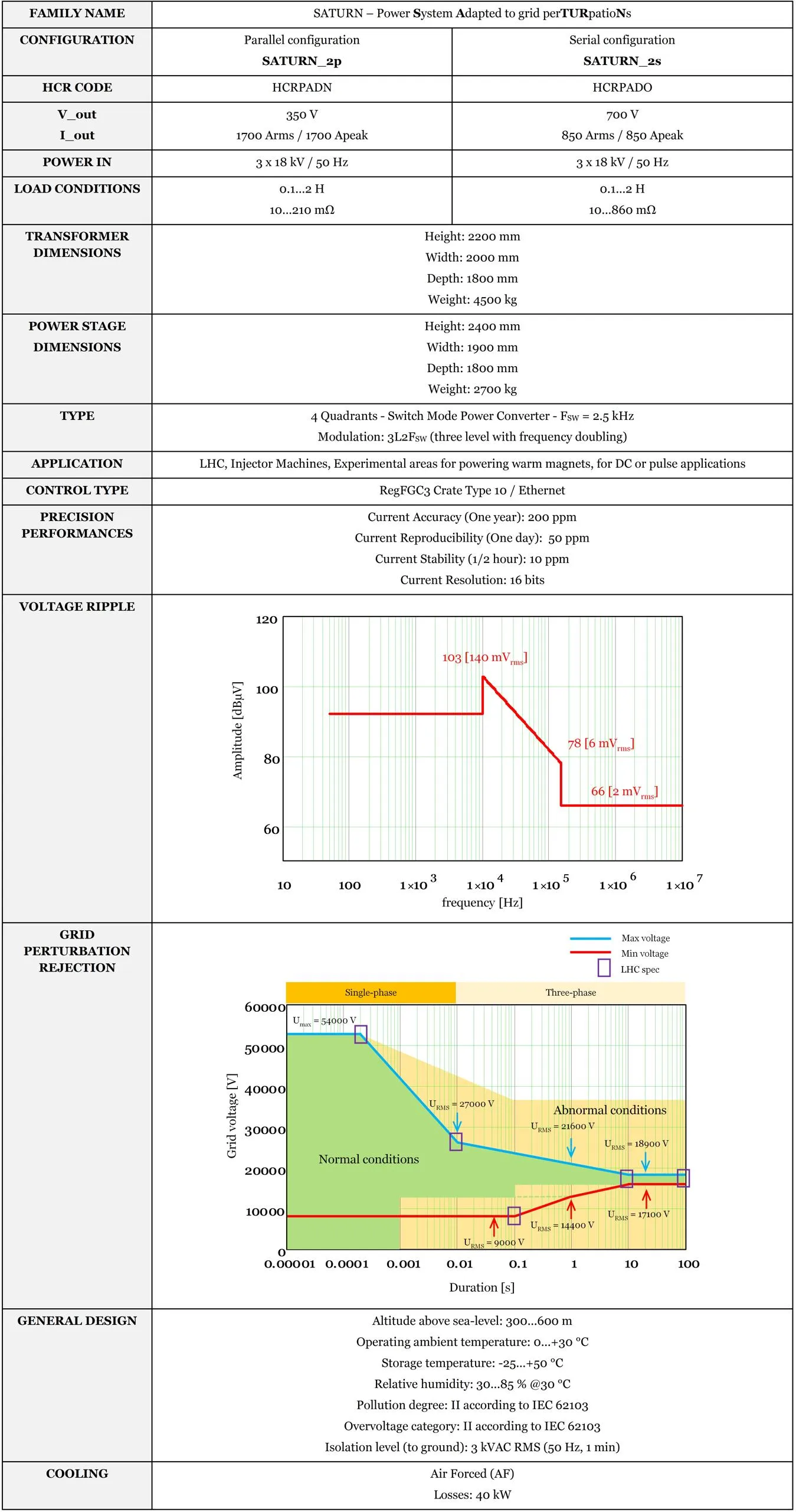
Power Converter Characteristics
Project Owner
Gilles le Godec
Project Team
Ivan Josifovic – Emilien Coulot – Stephane Reignier – Javier Parrilla Leal – Stefano Rossini – Christophe Mutin
Power Converter Responsibilities
Ivan Josifovic – Emilien Coulot
Power Converter Topology
The main power brick of converter consists of an 18 kV / 50 Hz transformer (for galvanic isolation, voltage adaptation and phase shift), a front-end diode rectifier with DC-link filter (for AC/DC conversion) and an IGBT H-bridge with output filter (for DC/DC conversion).
The energy of the magnet is:
- Recovered in a capacitors bank on the DC-link during cycling mode of operation;
- Dissipated in a brake chopper in case of insufficient energy storage in the DC-Link;
- Dissipated in a crowbar connected across output in case of fault.
Single SATURN module:
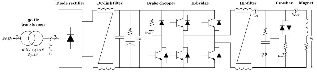
SATURN topology.vsd
Two SATURN modules are assembled in parallel to increase the current capability (SATURN_2p):
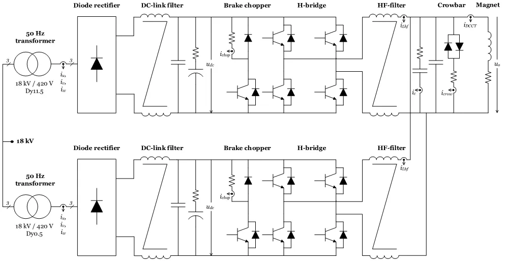
SATURN_2p topology.vsd
Two SATURN modules are assembled in series to increase the voltage capability (SATURN_2s):
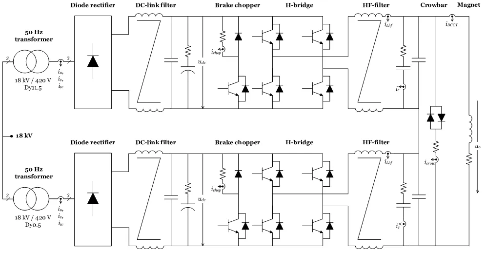
SATURN_2s topology.vsd
Magnet Protection
Power converter is part of magnet protection scheme, even if not directly fully responsible of the monitoring and diagnostic of the magnet status. PIC/WIC (Power/Warm Interlock Controller) can interlock power converter if magnet safety requires it.
Power converter is then expected to:
- Always ensure that external protection system can stop the power converter through a safe signal called Fast Abort.
- Stop powering the load in safe way (handling the magnet energy even when stopping, through dedicated system called Crowbar). This active system provides a safe resistive discharge path for magnet current (energy).
- Monitor earth current of the total circuit: converter + load (magnet and its DC cables), and take the right action if threshold reached.
► Active Crowbar
The system is based on axx Ω power resistor connected to two thyristors which are triggered when there is a faulty condition on the converter or when the voltage Vmeas goes beyond a predefined threshold (BOD protection).
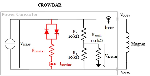
Crowbar system simplified schematic.vsd
Earth fault detection ►
The detection system is a passive solution which is independent of the configuration of the converter (serial or parallel). It’s composed of a voltage divider connected between positive polarity, the negative polarity and the earth:
- The voltage threshold VEARTH is set to 0.5 V hence limiting the fault current to 5 mA (REARTH = 0.1kΩ),
- R1 is chosen with respect to the requested sensitivity of the system:
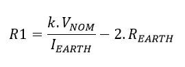
VNOM: Nominal value of the voltage,
k: voltage unbalance factor (0.05…0.1).
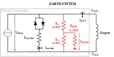
SATURN Earth System simplified schematic .vsd